
April 21, 2026 / by Fortify Labs / In teardown, technical, Komatsu, Mining, Heavy Equipment
Teardown: Komatsu
Satellite Telematics Module
Along with wonderful benefits to business functions, connected technology also brings risks.
One of our main goals is to generate discussion and critical thinking about the risks that this technology brings when they connect vehicles (and machinery) that is relied on to keep the country running.
In primary industries and critical infrastructure sectors, cyber breaches have the potential to impact much more than a company’s bottom line. A compromised fleet of vehicles could disrupt access to essential goods and services, effect employment, and ripple across multiple sectors of the economy.
In this blog post, we outline the initial steps we would take when conducting a vulnerability analysis on telematics equipment designed for commercial and industrial vehicles. Specifically, we examine a telematics module used to connect Komatsu machinery to external networks, the type of machinery that is commonly deployed on mine sites, construction sites, and similar environments.
A brief review of Komatsu’s website shows that this connected functionality is a core part of their business strategy. The data it collects and transmits help customers improve efficiency, save time, and reduce costs. However, once these critical assets are connected, cybersecurity becomes a crucial consideration.
In this post we:
- Disassemble the Komatsu Telematics Module.
- Characterize circuit board functionality though its physical components.
- Determine where the device firmware lives and download it.
- Perform a cursory analysis of the Firmware by examining its contents.
Device Details
- Make / Manufacturer: Komatsu
- Part Number: 7826-20-1050
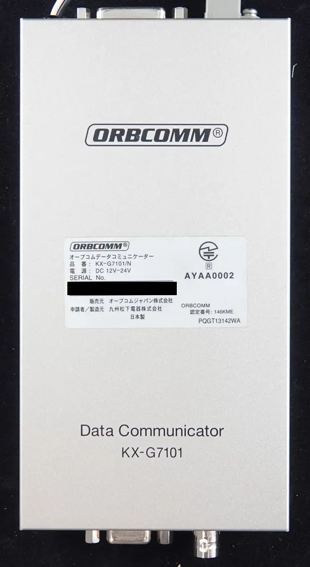
- Internal Data Communicator Manufacturer: ORBCOMM (The satellite/cellular telematics network provider - Global Data & Messaging)
- Internal Data Communicator Model: KX-G7101/N
The Telematics Unit
The Komatsu Controller is a telematics module designed for harsh operating environments and this one is designed to operate over satellite communications, indicating its intended use is for remote locations. It mainly contains a data communications module from ORBCOMM, a commercial satellite communications provider that operates global satellite constellations for industrial and commercial applications.
It interfaces directly with compatible Komatsu heavy equipment and is designed to:
- Collect operational data from the machinery.
- Acquire GPS location data.
- Transmit telemetry data via a satellite network back to a central management platform.
Teardown / Disassembly
This section provides an overview of the telematics unit disassembly process.
Step 1 - Removal of Outer Casing
- Komatsu Telematics Module - Outer Case
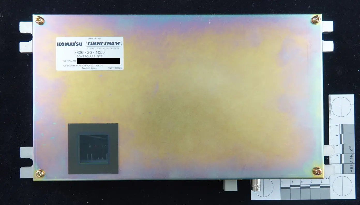
- Komatsu Telematics Module - Outer Casing Open
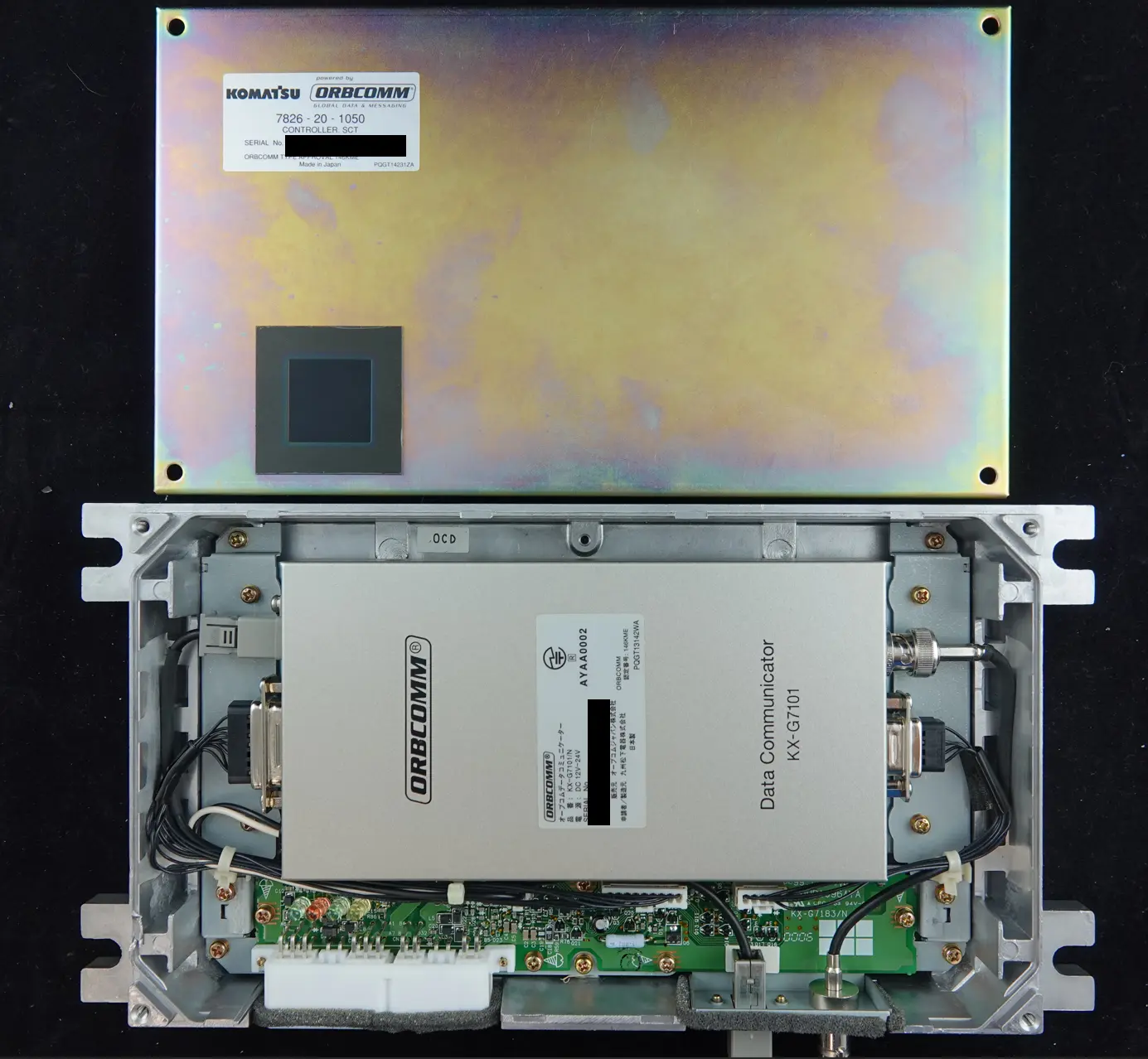
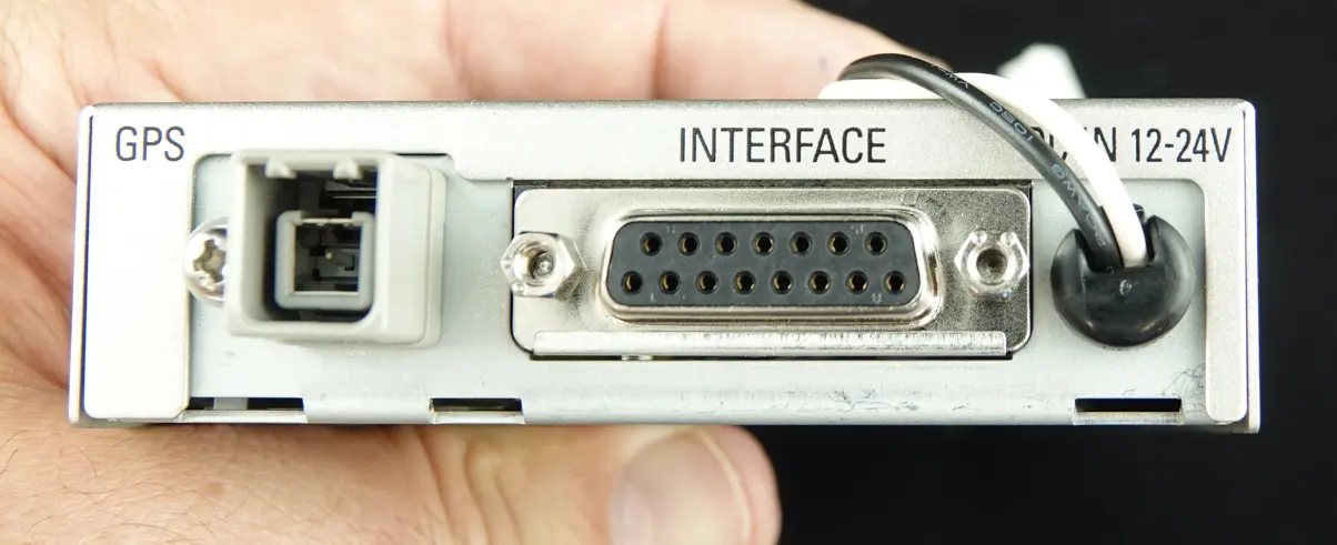
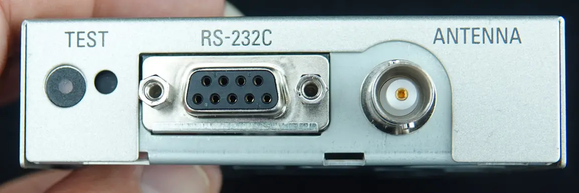
Step 2 - Removal of ORBCOMM KX‑G7101
- Remove all screws and connectors on the internal Printed Circuit Board (PCB) and remove the ORBCOMM KX‑G7101 module.
- ORBCOMM KX‑G7101 connectors
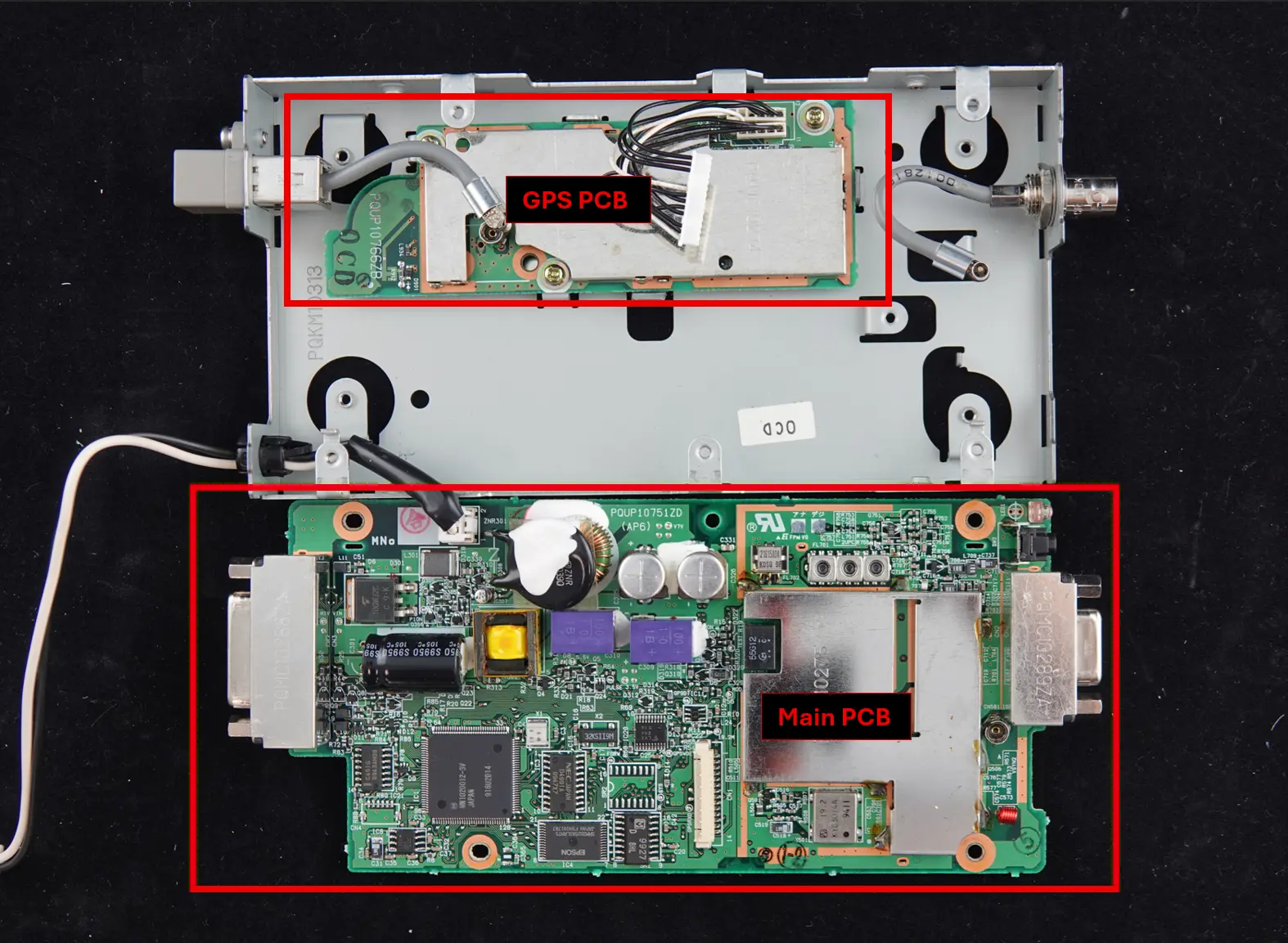
Step 3 - Disassemble ORBCOMM KX‑G7101
- Remove screws, Outer Case, and main PCB:
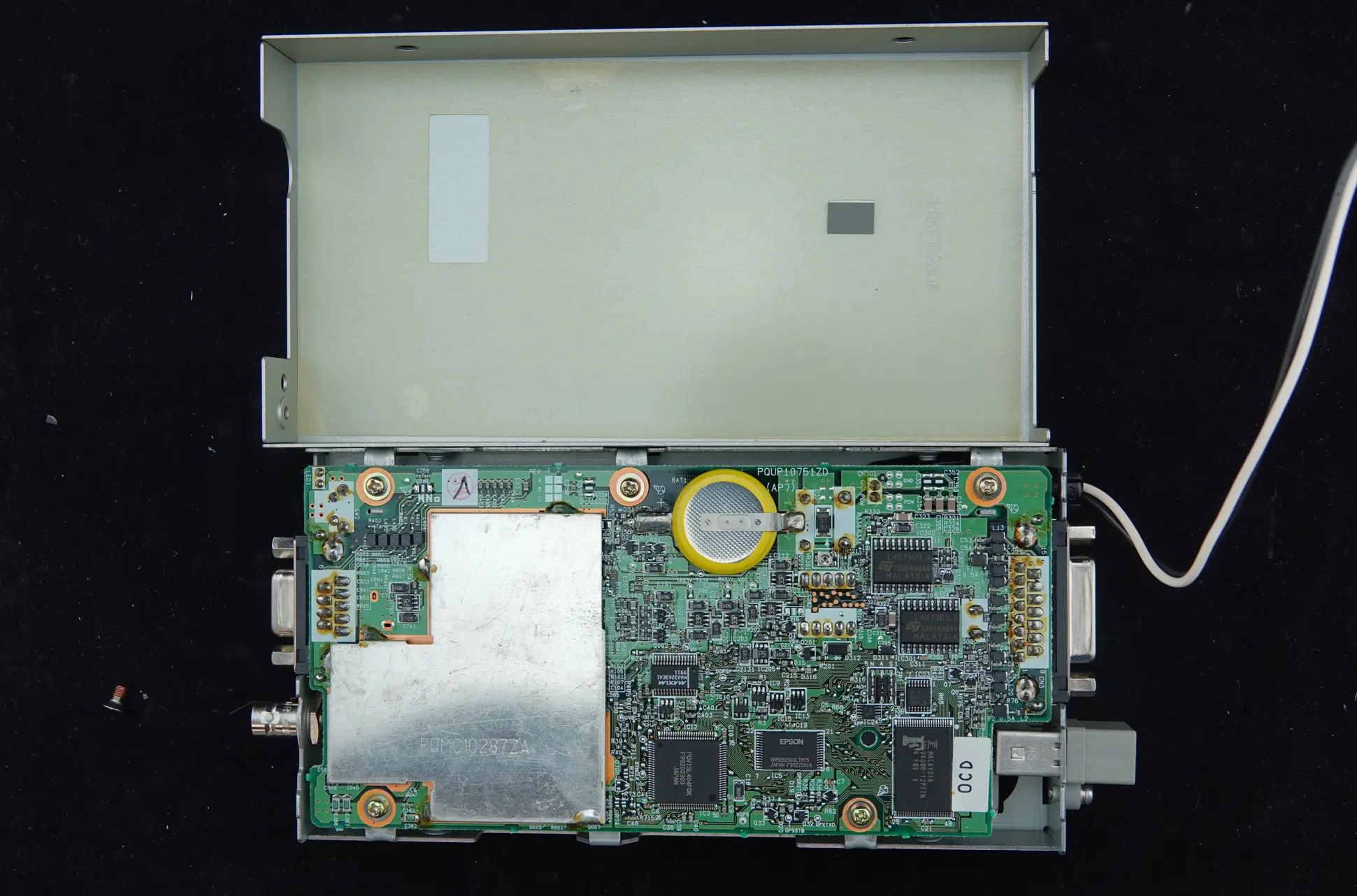
- Main and GPS PCBs
Step 4 - Remove / De-solder the Shielding on the ORBCOMM KX‑G7101 Main PCB
- De-solder / Remove the PCB Shielding
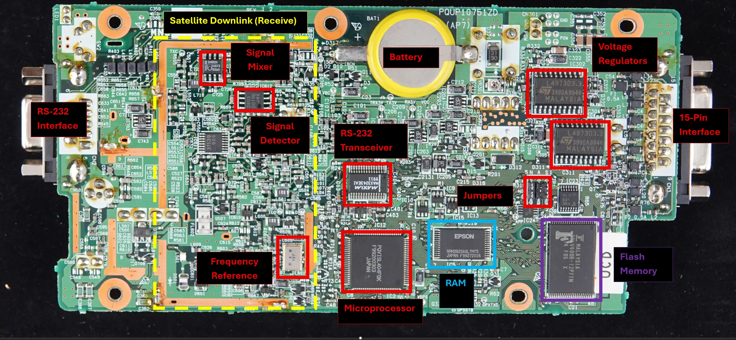
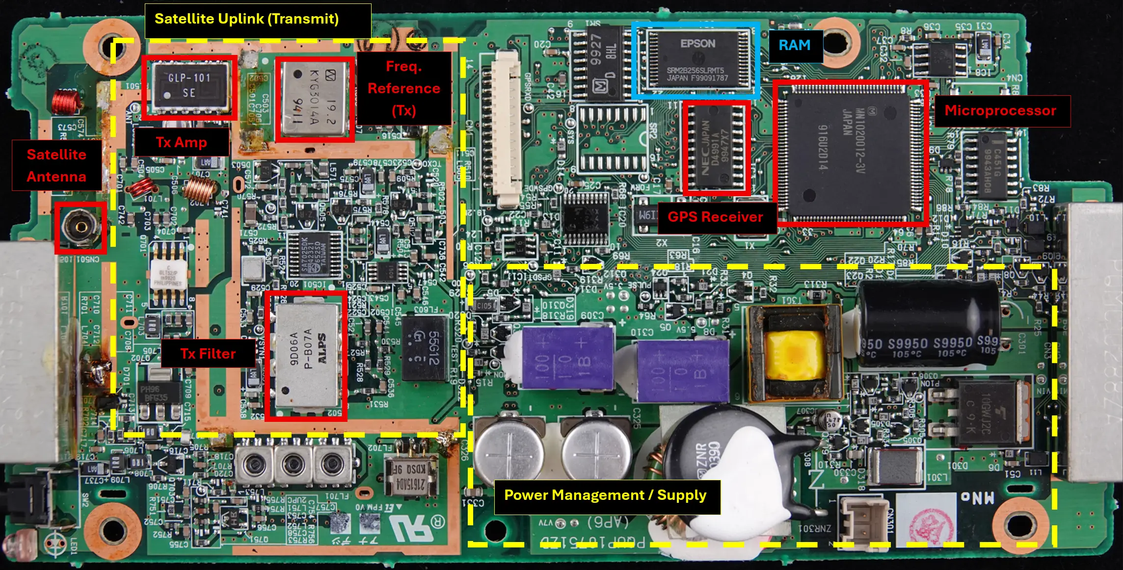
Hardware Breakdown - Board Characterization
During the characterization of the board, we found that the main components date back more than 25 years. This was interesting, as the design predates modern security‑by‑design principles, which were not widely adopted at the time these components were introduced.
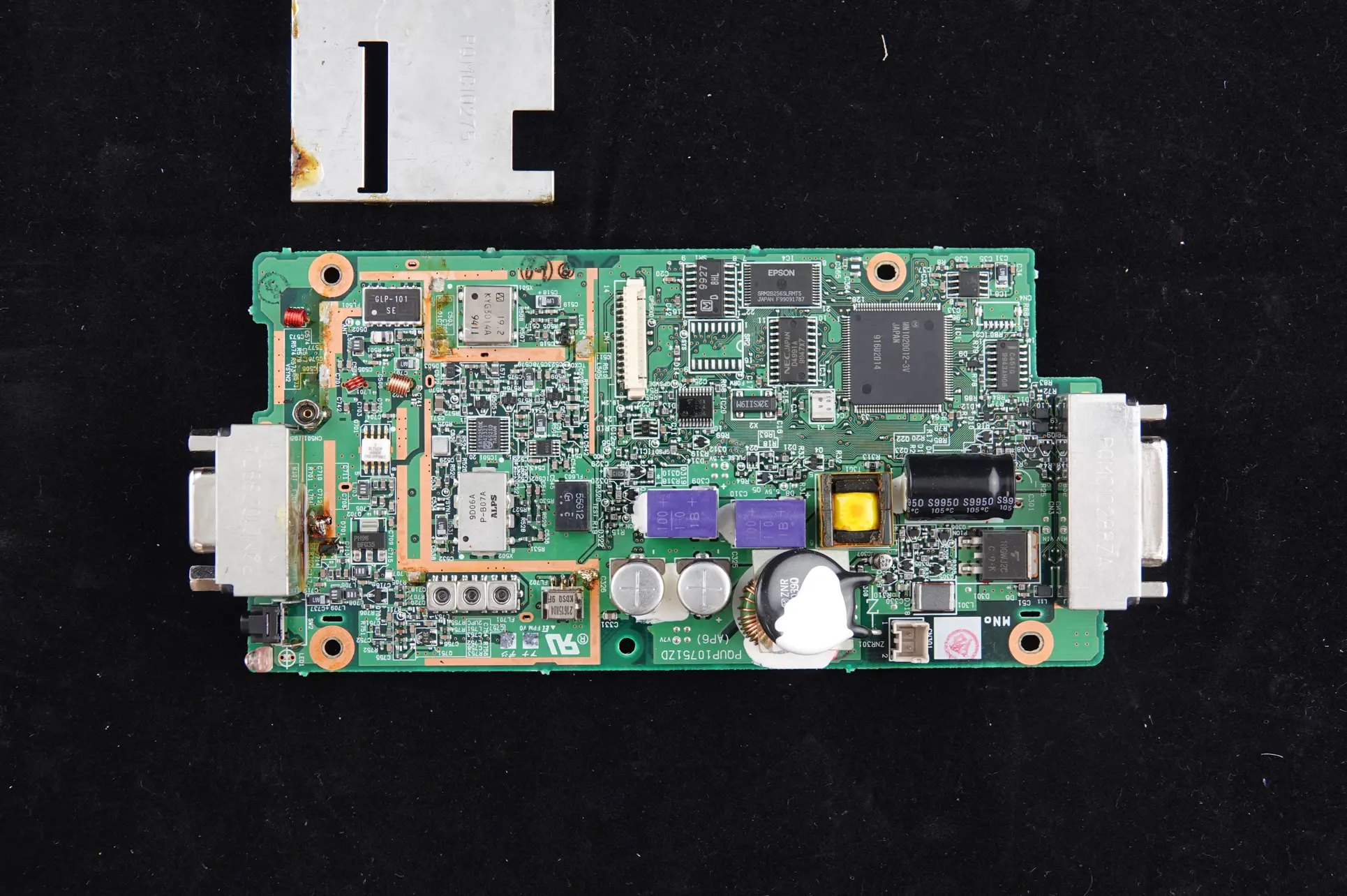
The following images show the internal circuit board and it’s main components:
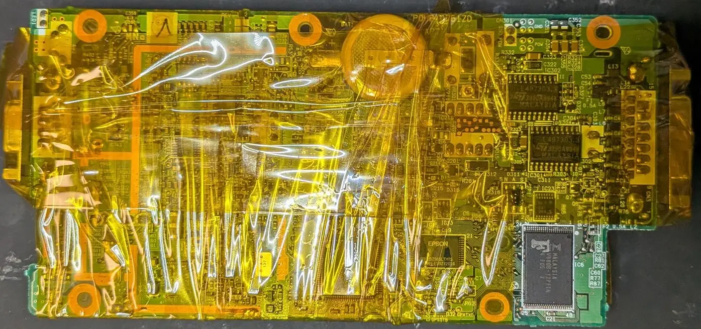
- Main PCB - Side 1
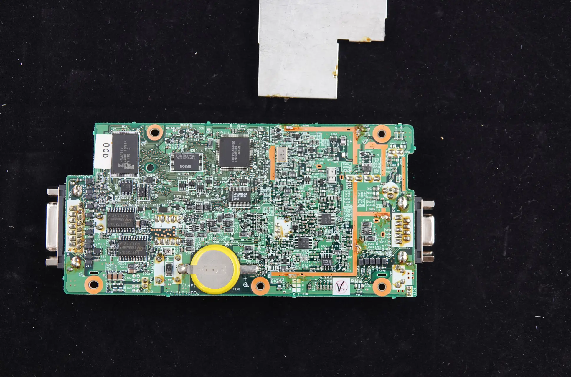
- Main PCB - Side 2
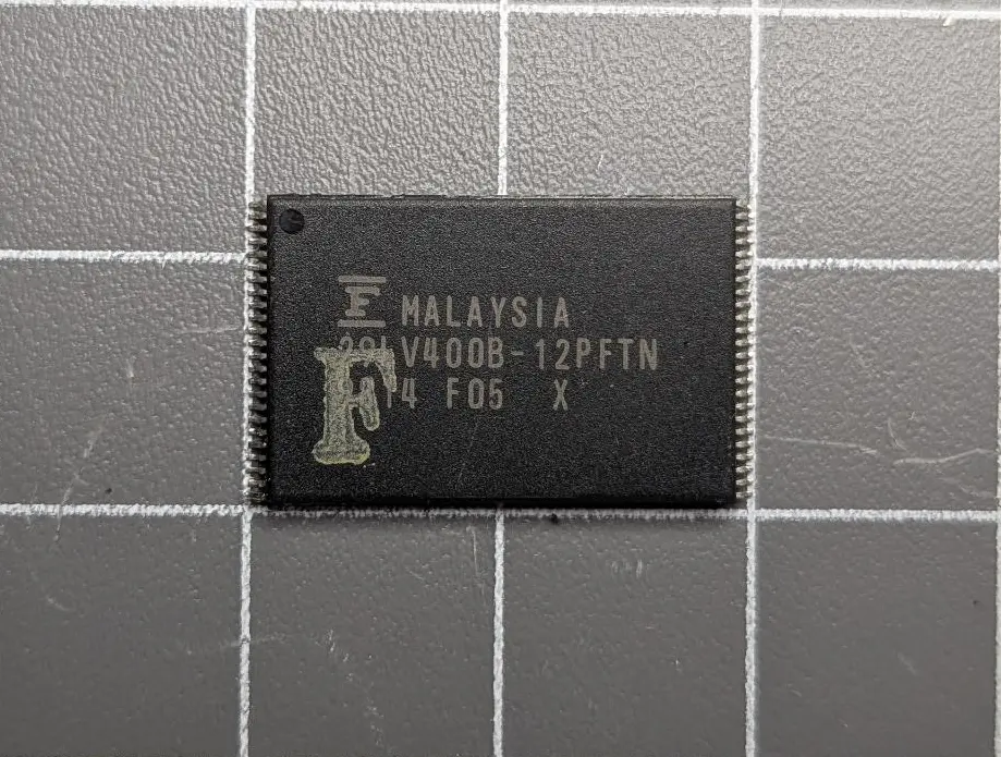
Flash Memory (Fujitsu 29LV400B-12PFTN) Chip Off
Based on the components identified on the board, the most likely storage location for the telematics module firmware is the Fujitsu 29LV400B‑12PFTN flash memory chip.
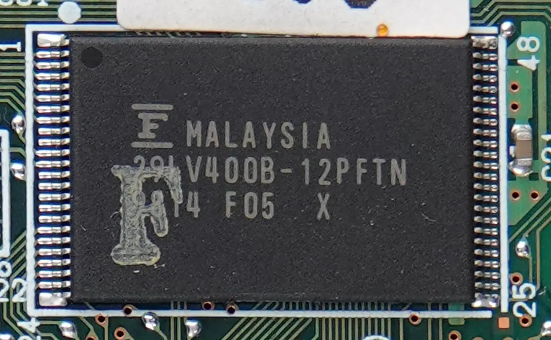
To enable firmware extraction, the flash memory chip was physically removed from the PCB so that its contents could be read directly:
- The PCB was protected using Kapton tape, exposing only the flash memory chip.
- We used our re-work station to heat up the board to the desired temperature:
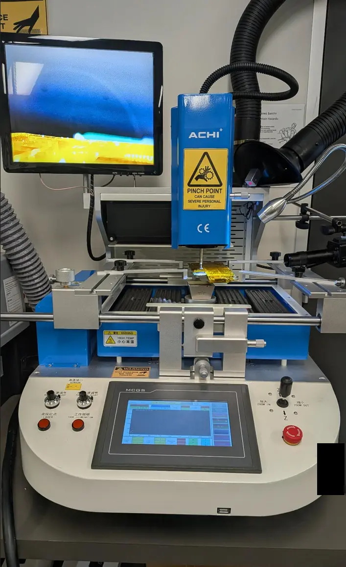
- The PCB was gradually heated from 160 °C to 270 °C, allowing the solder to reflow so that the device could be removed without damaging the pads or surrounding components.
-
Step Temperature (Degrees Celsius) Time (Sec) 0 Ramp up to 160 ~45 1 160 30 2 200 30 3 220 30 4 240 30 5 260 30 6 270 30 - Flash chip removed:
Memory Image - Firmware Extraction
With the chip removed, we extracted the firmware from the memory chip.
Equipment Used
| Item | Make/Model |
|---|---|
| Xgpro Software | v12.90 |
| XGecu universal device programmer | T56 |
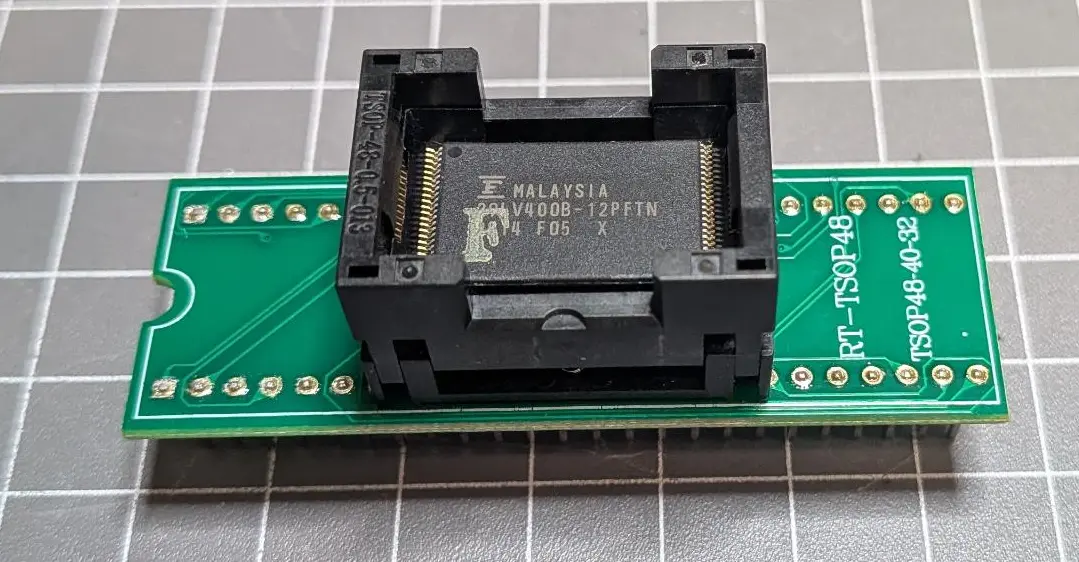
| XGecu Zif TSOP 48 Adaptor / Caddy | RT-TSOP48 / TSOP48-40-32 |
-
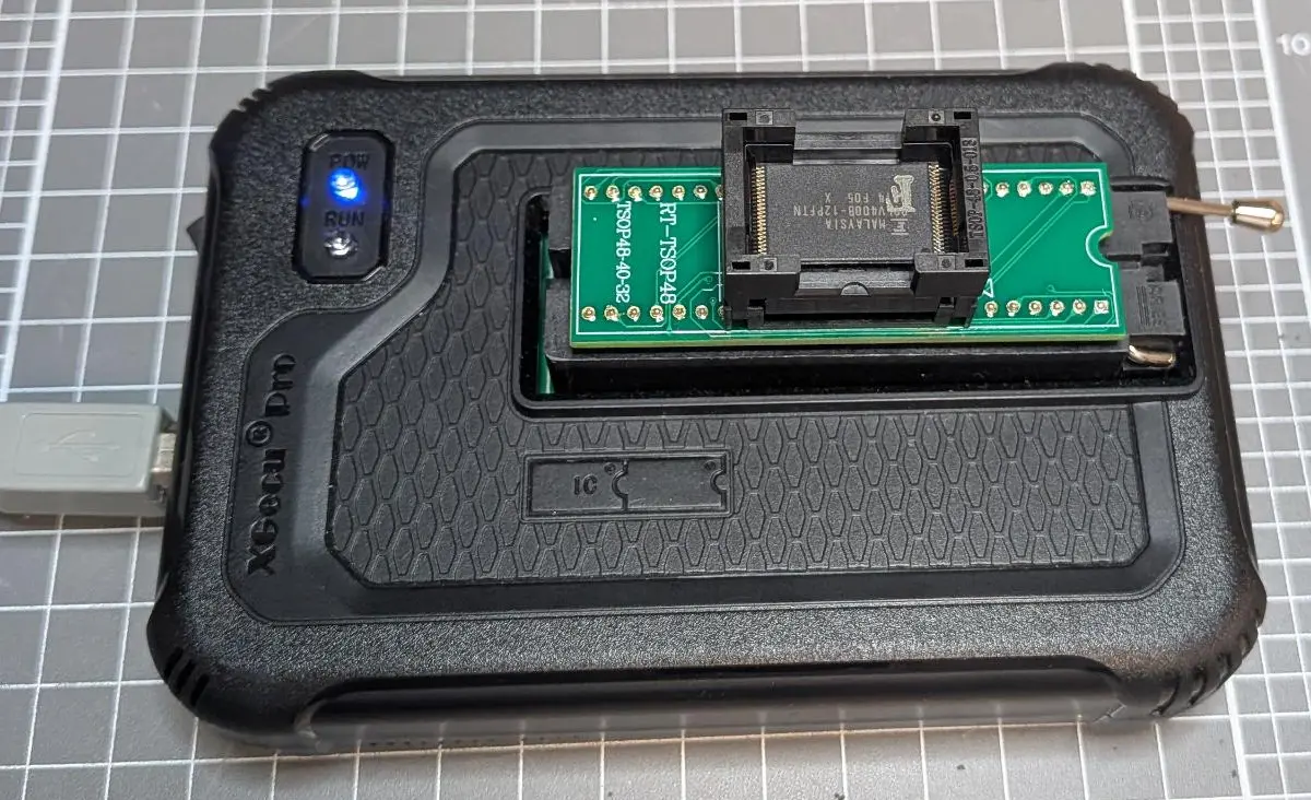
The flash memory device was inserted into the TSOP‑48 ZIF adapter:
-
The adapter was connected to the the device programmer.
-
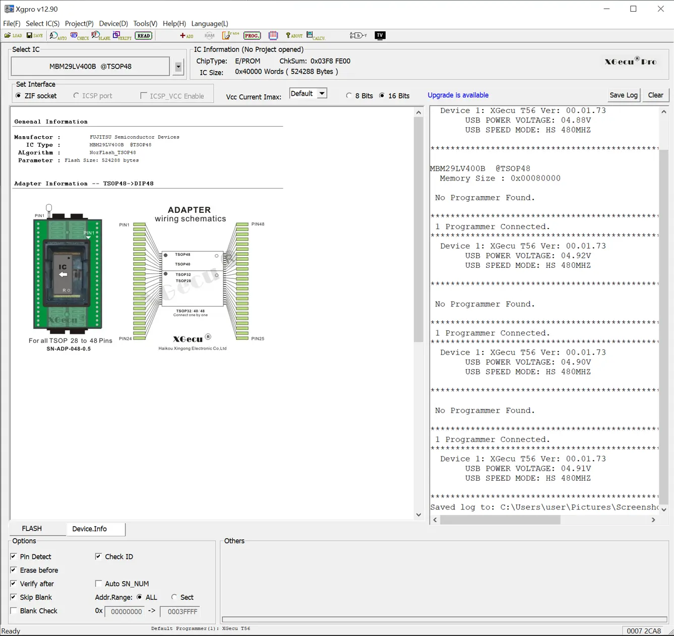
Within the Xgpro software, we selected the profile for our chip (FUJITSU MBM29LV400B @ TSOP48):
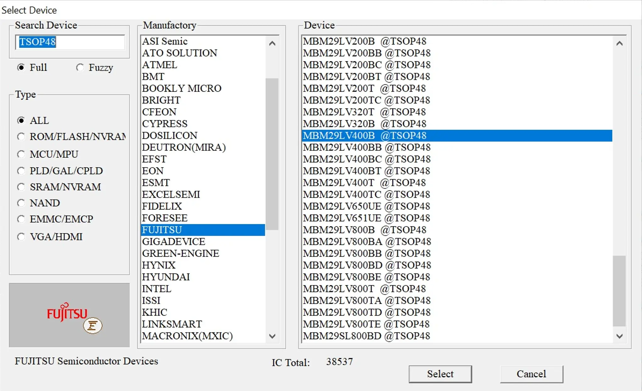
-
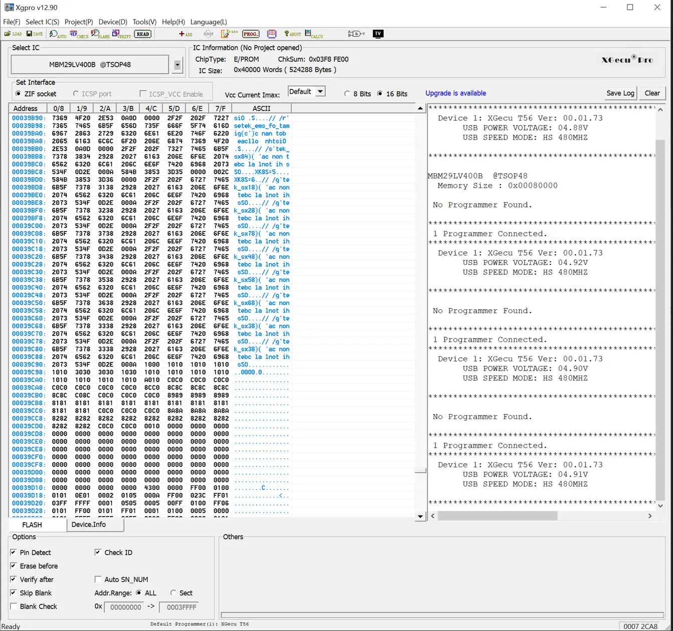
The chip’s memory was then read and a binary image created:
Analysis of Firmware
A comprehensive firmware analysis can be time consuming and resource intensive. For this project, we performed a targeted analysis aimed at getting an initial understanding of the telematics unit’s functionality by examining human readable strings embedded within the firmware.
Note: If you’re interested in a deeper firmware analysis, please contact us. We’re happy to discuss expanding this work into a future blog post.
String analysis is often a valuable first step in firmware research. Meaningful strings can reveal function names, debug messages, developer comments, or other snippets that provide clues as to how the firmware behaves without requiring full reverse engineering.
To begin, extracted the strings with this command:
| Item | Note/Link |
|---|---|
strings command |
$ strings -n 6 MBM29LV400B@TSOP48.BIN > strings.txt |
| Firmware Strings Analysis Writeup | Writeup Page Link |
| Firmware Strings — Meaningful String Extraction | Link to Text File |
A review of the extracted strings revealed information about the firmware’s structure and capabilities, without requiring full disassembly. Notable findings include:
| String | Description |
|---|---|
X2C1F-002 |
Firmware version |
1999/08/24 |
Manufacturing Date |
--- O_MAIN() START --- |
Firmware entry point |
USER_RAM CLEAR |
First Instructions Comments in the entry function |
USER_MEM CLEAR |
First Instructions Comments in the entry function |
XMODEM Protocol Starts. Start Sending 2nd Loader Software within 10sec. |
Indications of an XMODEM-based firmware update mechanism |
ENG_REV |
Vehicle telemetry data - engine info |
ENG_W_TMP |
Vehicle telemetry data - engine water temp |
PMP_PRES |
Vehicle telemetry data - pump pressure |
CAUTION1 |
Vehicle telemetry data - caution/warning information |
CAUTION2 |
Vehicle telemetry data - caution/warning information |
--------------- [ ] GENERAL ------------------- |
Diagnostic menu strings - indicates that the firmware includes methods to interact directly with it |
--------------- [1] SAT_LOG_1 ----------------- |
Diagnostic menu strings - Satellite log menu entry |
--------------- [9] GPS_DATA ------------------ |
Diagnostic menu strings - GPS data log menu entry |
The jumper connection JP1 was set to illegal position. Set it to the 'A' position. |
Indications of board jumper functionality |
Conclusion
Even this lightweight analysis highlights several important characteristics of the firmware, including legacy design age, support for diagnostic or interactive menus, telemetry collection scope, and a firmware update mechanism that may warrant closer scrutiny during a more in‑depth security review.
We wrapped up our analysis at this stage and did not analyse the firmware to a deeper level. Please contact us should you wish to discuss a deeper analysis of the firmware or vulnerability assessment.
Fortify Labs Github Repository
Please visit our Fortify Labs Automotive Forensics Github repository for additional tools related to our Automotive research.
Disclaimer
This analysis is based on our professional experience and reflects our best interpretation at the time of examination.
Anyone choosing to replicate these procedures does so at their own risk.
Disassembling a vehicle (or equipment) and interacting directly with its electronic components carries an inherent risk of damage to the equipment. Fortify Labs does not guarantee that any procedure described will be free of risk, nor do we accept responsibility for any resulting damage.